Wednesday, December 23, 2015

Update: Give Me Some Slack!


The birds eye view of a wire run doesn't account for running up and down the wall, or running from one floor to another.  To accommodate this, there is a new input where you can type in a number to add to the calculated wire length.

Click on a wire to make it active, and enter a number into the "Wire Slack" number box.  Press the "Set" button to save the new value.  If you have split a wire into multiple wires, choose the wire with the length label and add slack to it.

With this new menu item, the wire menu started getting a bit crowded.  Some of the other menu items have been moved to a Wire Menu to the right:


This menu houses the "Split Wire", "Straighten", and the "Remove Wire" functions.

The tutorial videos have not been modified yet with this new layout but will soon.  We continue to add features so please keep the requests coming!


Thursday, December 3, 2015

Feature Update: Add Pictures of Customer Systems through Techforce Pro Mobile

Whether you are a technician troubleshooting a customers issue, or a sales rep doing a walk through, being able to attach real pictures to systems you install is vital when troubleshooting and integrating a system.

Techforce Pro is now the only software available that makes adding pictures to a customers file an easy task.  Simply find the system on the customers floor plan, and take a picture.  The picture is immediately available to anyone else viewing the customer through Techforce Pro Mobile, or TechforcePro.com.

First, find the system that you want to add a picture to.


In the section at the bottom, you can view existing pictures, or take new ones.


Clicking "Add Picture" opens the camera for you to take the picture.  Once the picture is taken, it is added to that systems pictures for viewing.

Clicking the picture thumbnail opens the picture full size for a more detailed view.


Open the system in TechforcePro.com and view the pictures there as well.


Sharing pictures has never been easier.  Seeing the system empowers your team to make better, faster decisions which ultimately makes for happy customers!

Tuesday, November 24, 2015

Tutorial: Adding Parts to Techforce Pro

Can't find a part you need.  Let us know and we'll get it in for you asap.  But if you can't wait, you can add your own parts to use in your wiring diagrams and as-builts.  To access your parts library, click your username in the upper right, and click on "Our Parts".

On the parts page, you can create organize your parts into Catalogs and Series.  A Part must be in a Catalog or a Series.

A Catalog holds Series and Parts, and a Series only holds Parts.  For example.  If I had a Catalog called "Managed Switches", I could have a set of Series called "5-Port", 8-Port"...  Inside the Series would be the actual parts.  Catalogs and Series have a folder icon, and Parts have a gear icon.


Click on one of the blue buttons along the top to create a new Catalog, Series, or Part


At least one Catalog is required.  Click the "New Catalog" button and complete the form.  The new Catalog will appear in the left menu automatically.


If you want, you can start adding Parts now.  Or if you need to add any sub-series to the Catalog, click the "New Series" button, and complete the form.  The only new item you see here is a check box for the Catalog you want to add the Series to.  You can add the Series to multiple Catalogs if you like.  For example, night vision camera's might go under a "Night Vision" Catalog, and a "Outdoor" Catalog.


Now the fun, adding Parts.  Click Add New Part to open the Part Creator.  There are two main sections. The part creator at the top is where you select the image, and add terminals. The details section below is where you enter a Title and Part Number, and select which Series and/or Catalogs the Part should appear in.  You can add this part to any number of Series or directly in Catalogs to help people find your parts easier.

Lets start with the top part and create the image and Terminals.


This is where you can choose your parts image, re-size the image if it is too large or small, and edit the terminals.  Start by clicking "Change Image" to open a file browser and find your picture.  The picture will appear in the same size that it will appear in the Diagram Editor.


We added a timer relay.  The thumbnail in the upper left is how this part will be displayed when added to a floor plan.  Now that we have the image, it can be re-sized if needed.  The main reason for re-sizing would be because the image is too large and takes up too much space on the wiring diagram, or it is too small and the terminals overlap.  We'll revisit this in a minute.  First let's add terminals.

Terminals are directional.  When you move parts around on the wiring diagram, you want the wires to maintain their direction so it is obvious where they are connected to.  The short animation below shows adding terminals to this part.


You can drag a terminal into place, or use the sliders for more precise placement.  Notice that when another terminal is added, it appears above the previous one.  This makes it easier when adding many terminals to one side.  Start by adding one to the bottom for the best use.  When adding terminals pointing up or down, they will appear to the right of the previous.

If your image is large, but has many terminals, you will still want to keep the image large enough so the terminals don't overlap.  The person making the wiring diagram will need to use a larger workbench to accommodate the larger part. 

If you find that you need to re-size the part after adding a few terminals, it would be easier to restart than re-size and move the existing terminals back into place.  Restart by refreshing the web page.  This short animation shows re-sizing the image.  Hold the shift key to maintain the aspect ratio.


That's the hard part.  All that's left is adding a title, part number, and choosing what Catalog(s) and Series this part will be displayed in.

One last important note: The parts are live in the wiring diagrams, so if you change an image, all diagrams will take on that new part image.  If you move terminals around, those will be moved in diagrams.  So once you create a part, be sure to make any edits right away before it is used.  You cannot delete parts, only obsolete them.  Obsolete parts will not show up in the diagram creator.

Wednesday, November 18, 2015

Browse Floor Plans and System Diagrams on Mobile!

Techforce Pro Mobile for Android has received an update on 11/18/15.  At first it may not look like much has changed.  But now, instead of just being able to view your jobs, you can browse all of your customers and system diagrams.

Clicking on the menu button, or swiping to the right opens up the menu


From the menu that appears, you can choose Systems, Customers, or Jobs, just like TechforcePro.com.  We'll start the tour by going into Customers:


Here is your full list of customers.  Use the search box to filter the list.  Clicking on a customer takes you to a details page:


Here you can see some basic details like the date this customer was added, the list of floor plans, and a full customer part list with images and quantities.  Clicking on a floor plan takes you to a page with more details about the floor plan.


You can get a preview of the floor's as-built diagram, along with a list of diagrams and the labels they have in the as-built.  Clicking on the as-built will take you to a full size image of the as-built where you can pinch to zoom and move around the floor plan to find what you are looking for.


Here you can see we found an electrical closet with a system number 13709.  To view this system in details, go back to the previous page, find the system and click on it.


Click on the System Diagram to view it in the image viewer to view it full size.


In fact, any image in TechforcePro Mobile can be sized larger for a better view.  Next, we go back to the side menu to enter the Systems page:


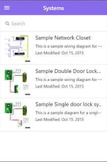
The Systems page has your list of systems that are not in a folder, those in folders will be coming soon.  These systems can be filtered by typing into the search box at the top.  Clicking on a system takes you to the system details page you saw previously where you get a part list and see the diagram full size.

That's it for this update.  Keep the suggestions coming!  Apple mobile update is coming soon.

Friday, October 30, 2015

Automatic Wire Run Lengths


Often, when creating the initial floor plan diagrams, you wire systems and parts together without regard to wire length.  The length a wire travels is a vital component to the functionality of your systems.  Wires have resistance and the voltage available at the other end of a DC wire run is not going to be the same as what is at the power supply.


Now, with Techforce Pro, your wire lengths are automatically available to you based on the scale you set to the floor plan.  To enable this, press Menu, then Settings:


In the settings menu, you will now see an option to Show Wire Lengths


Check this box and all of your wire runs will have a label indicating the distance based on the scale you set.  Remove the check to hide the lengths.


If your wire run has been split and includes handles, the entire run excluding the handles will be calculated and the label will appear near the middle of the whole wire run.  Change the scale, move parts and systems around and view all the numbers change automatically based on your changes.  

You will still need to know your own limitations but Techforce Pro now telling you the run lengths takes one more time consuming task out of your hands.


Tuesday, October 20, 2015

Feature Update: Shapes and Scale on the Floor Plan


This week, the new feature added to Techforce Pro is adding background shapes and adding a scale to your floor plan.  Adding shapes is helpful when showing the direction of a camera, the coverage area of a wireless receiver, or highlighting areas of the floor plan.

You can find the "Add Shapes" option under "Menu"


Here you see options to add geometric shapes, or enable free drawing.


After you add a shape, you can change interact with it directly to move it, rotate it, and re-size it.


Use the anchors around the shape to re-size it, and the one extending handle to rotate it.


Use the menu to change the shapes color and opacity (transparency).


All shapes appear behind diagrams, parts and wires.


Another item you can add is free drawn shapes.  First, make sure the area you want to draw on is visible on the screen.  The website has to lock the floor plan in place when free drawing so the floor plan doesn't move.

Next, Click "Enable Free Draw".  You can jot down a note, or circle a large area.


If you select a color, the free drawn shape will close it's path and fill in.  If you are jotting a note, you do not want to do this.


Any shape can be removed by selecting it and clicking "Remove" in the lower right corner so you can remove temporary notes later on.

The second update is adding a scale to your floor plan.  For now it is just a visual indication, but we plan on taking this a bit further in the near future, (like calculating wire run distances).

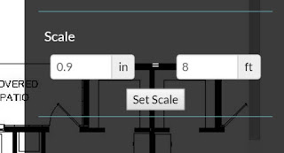
To show the scale, click on the menu and Settings.  A new section under "Scale" is where you can type in your inches to feet conversion.


When you press "Set Scale", a scale will appear in the upper left corner of the floor plan.


Fine tune this by dragging it to an area on the floor plan that you know the real distance, such as an 8 foot hallway, and better define the scale there.


When you have it right, drag the scale to it's final destination.  for any shape, to straighten it out, click the "Straighten" button to snap the shape, or the scale, to the closest 90deg rotation point.


Wednesday, October 14, 2015

Feature Update: Re-sizable Icons on the Floor Plan

When you add a part or diagram to a floor plan with Techforce Pro, they may fit properly depending on the size of the floor plan.  However if your floor plan is smaller, these icons will start to get close to each other or even overlap.

Next time you modify a customers floor plan with Techforce Pro, you will have the ability to modify what you see in the icon and how large it is.  To change these settings, first click on the menu button:


As you can see, there is a new option, Settings.  Pressing this opens a new menu where you can show or hide part or system Icons.


In this example, I'll turn off the "Show Part Icons" check-box.  Notice in the image below, the part labeled "A6" no longer has an image.  When you print up the customer PDF, or view the floor plan details page, you can still reference the part using the "A6" label.


Next, I resize the icons by pressing the minus - button in the Grow/Shrink Item section of settings.  Notice in the image below that the text size and images are much smaller.  I am zoomed out of this floor plan so on the final image, these labels are readable.


This will be helpful when you have many items on a page that are close to each other, like smoke detectors in apartments, or sensors in hallways.  Everything is still able to be wired up as normal.

As usual, keep the feature requests coming.

Ben Felda
Techforce Pro
www.techforcepro.com


Monday, September 28, 2015

We need more Wire Colors!

We have had requests for more colors and until now we have been adding them as requested.  We scrapped that and added all named colors for you to choose from.

Like before, when you select a wire, a set of typical colors will be available


You can choose one of these colors, or, when you hover over one of them, a set of more options becomes available


This is used for changing colors in the system diagrams and the floor plans.

As always, keep the feature requests coming!


Monday, August 3, 2015

Using Techforce Pro to make Awesome As-Builts

Techforce Pro has been known as a tool to make professional wiring diagrams.  Now use Techforce Pro to put together your As-Builts.  This post will show you how to upload a floor plan and place your wiring diagrams, or individual parts on the floor plan.  Then wire them together, add labels and notes.

First, go to your Customers page and click on "New Customer":


Enter the name of the customer and press Save.  This will take you to the customers overview page.

Click "Add Plan" and enter the name of the floor plan.


After saving the floor plan title, click on the newly added floor plan to enter the as-built builder:


Click the "Upload Floorplan button to select a PDF, or image file.


If you upload a pdf, the image must be on the first page of the pdf.
When your floor plan loads, you can click the menu button in the lower right to add notes, parts and diagrams


Drag the Notes, Systems, or Parts to the proper location on the floor plan, then start wiring them together


You connect them together.  To connect two systems or parts, start by clicking on the item where the wire will start.  In this case, I'll click on the mechanical closet.


This brings up a popup with options for this system.  You can remove the system from the floor plan by clicking the button in the menu bar at the bottom.  You can add a label to the system for a unique identifier for the system on the floor plan in the lower left.   But the reason we are viewing this now is to add a wire as the wording along the top states "Choose a direction to start a wire run".  Because the system I am connecting to is to the right of this system, I'll click on the right arrow.  After clicking the arrow, you are returned to the floor plan.

Next click on the system that the wire run goes to.


Notice that the working across the top says "Choose a direction to end a wire run".  In this case, I'll click the bottom arrow.

The wire is now created and you can manipulate it with the buttons in the menu bar at the bottom.  You can change the color and manipulate it's position, or remove the wire run entirely.

Next, I'll add a note by clicking the Add Note button in the menu


Drag the note where you want, click on it to edit the text.  Click anywhere to get out of edit mode.

Clicking save will save the as-built and take you to an overview page


On this page you can save the as-built off as a full size image file, edit the plans title and give it a description, or go back and edit the as-built.  Below the as-built image are two lists, one of the diagrams and one of the parts in the as-built.  Clicking on one will highlight it on the as-built so you can get a quick view of where they are installed.

Clicking the back button takes you back to the customers page where you can see the parts list populate with the parts from the newly added systems and parts.  Clicking "Export Customer PDF" will save the whole customer file off as a pdf with the as-builts, wiring diagrams, and full part list.