Friday, December 29, 2017

TFP Preview: Don't show it all on one floor plan!

Earlier this year, we released a feature where you can group the items on your floor plan.  You can put all your red wires in one group, and hide/show them as needed.  This helped alleviate a busy looking floor plan, but it still wasn't a perfect solution to the problems I saw happening.

After discussing with many of you, we came to the conclusion that one layout per floor plan wasn't enough.  You needed the ability to have a multiple layouts for the same floor plan.  Such has one floor plan showing power runs, and one floor plan showing the network runs.

Were not done with this feature yet, but we are far enough to give you a preview and get your feedback.


Friday, June 9, 2017

How Much Wire does a Job Need? Answered!

Techforce Pro has an awesome feature where you can set the scale of a floor plan and see the wire length of each wire run, even adding slack to the run to compensate for vertical runs and in-between floors.


But what about when you have to estimate how much wire the floor plan has all together, or for that matter, how much wire the customer has so you know how much to order.  Techforce Pro now helps out with this by adding up your wire runs per floor and displaying them at the customer level, and floor plan level.  Know exactly how much wire of a certain color is configured to be used for the customer when you are done creating your floor plans.


Now remember, Techforce Pro can only measure the wire run distance as the bird flies, so if you think there should be added slack to a wire length, be sure to add it.  And even with that, round up and add a bit to your order.  But this should give you a quick estimate to help out when you are ordering wire.

You will need to correlate the colors to a specific wire type, like using blue wire for CAT-5 or red for power.  Down the road we will be adding a means for setting different names to the colors to help out with this.

Saturday, December 24, 2016

Group items on your Floor Plan


If you have been using shapes to space your parts apart, you probably don't want those shapes showing up when you save the image.  There also may be other parts, wires, or systems that you don't want to show in the final drawing.

Step 1 is to create the new group.  You will want to name it something that is easily understood, such as "Red Wires" or "Smoke Detector Spacers".


The next step is to apply the group to the item by selecting the shape, system, part or wire, and changing the group.  Thats it!  You can then go back to the group and hide or show it by clicking on the eyeball.


Thursday, September 29, 2016

TFP Update: Rotate your Floor Plans

You scan your floor plan and upload it to Techforce Pro only to find that you scanned it upside down or sideways.  Not a problem anymore.


Click into your plan settings and at the bottom, you will find two new buttons to rotate the floor plan 90 degrees to the left or right.  Click multiple times to rotate 180 degrees.  This can be done at anytime.

!Important Note:  Rotating the floor plan image does not rotate the parts, wires, systems or notes added to the floor plan.

That's it, very simple addition to Techforce Pro.  Please comment below with any questions about this new feature.

Tuesday, July 12, 2016

Techforce Pro Update: Set Parts Equidistant from Each Other


Placing parts repeatedly on a floor plan is a common task.  Smoke detectors need to be placed every 30-40 feet, and wireless access points need to be placed about every 150 feet.

Techforce Pro is making this task easier by using shapes to properly place parts at equal distances to each other.

  1. Add any shape (typically a circle)
  2. Type the proper size into the "Size" text box and press the "Set" button.


Tuesday, April 12, 2016

Feature Update: Share Floor Plans with Sub Contractors easily with Techforce Pro


Techforce Pro is a great tool for creating and sharing your wiring diagrams and customer floor plans with your staff.  But what if you want to share this information with a third party sub-contractor.  There is a good chance that your company isn't the only company on the job.  You can print up the pdf needed and email it to them, but it would be nice to share the customer floor plan with them the same way you do with your own staff.

Techforce Pro now lets you create a partnership with other Techforce Pro members of any subscription level, even the free version.  You send them a partnership request, and when they accept, you can share your customer information with them.

If you don't want them to have the ability to edit the information, you can give them read only access.  This will allow them to add pictures to wiring diagrams, and schedule their own staff for service calls for this customer.  They will not be able to edit the customer information including the floor plans, or wiring diagrams.

If you want them to create as-built diagrams, you can give them full access and they will be able to edit the customer information as though they were on your staff.

This feature is secure but still experimental, and is open for all to try out.  This is the first installment of many updates around this feature such as:

  • Only share your parts to be used in diagrams with your partners
  • Share service calls with your partners
  • Share the systems not in customer facilities with your partners (good for training and removes the need for manuals)
Let me know what you think and give me feedback on what you like/dislike.  

Monday, March 7, 2016

New Showcase Videos for Techforce Pro


We have added many new features over the past six months.  Time to remember why those features are in place.

The three videos in the above playlist introduce the problems that Techforce Pro fixes.  They are common problems that have plagued the security, fire security, and home automation industries for decades.


Video 1: System Diagrams:
I was a field technician for much of my career.  Something that always bothered me was seeing wiring diagrams written on napkins, or chicken scratched together.  There are tools for showing workflows like Visio, and there are tools for making circuit board diagrams, but nothing for making system for this industry.

Techforce Pro's initial goal was to create a site where you can easily create wiring diagrams with the real parts from the manufacturer, and share them with colleagues via mobile device, web or paper. Partner this with the ability to add your own parts quickly and you have a great tool for managing your system diagrams.


Video 2: Customer Management:
Adding the systems and parts to a customers floor plan is typically done with the same cad tool used to create the floor plan.  This results in a drawing, but no way to tie the drawing to what is actually on site.  There is duplicate work that is needed to keep the drawings up to date, and typically, they get out of sync.

Techforce Pro is the only tool that allows you to add the wiring diagrams you created, and real parts you use, to these floor plans.  Wire lengths are calculated, and part lists are created based on the scale you set, and the parts/systems you add.  Now, create interactive, live floor plan drawings that will keep in sync with future changes to the customer.


Video 3: Jobs and Service Calls:
As a field technician, another pain point I had was receiving a service call with hardly any information about what is broken.  The customer already called in, told someone enough information to deem a service call worthy, but I am going to get on site and have to ask all the same information.

What if it is something I haven't worked on before?  What if I look like I don't know what I am doing in front of the customer?

Your technicians need to at least appear to know what they are doing when they get on site.  Your technician needs confidence, and your customers need trust.  Techforce Pro jobs and service calls can be created by anyone as long as they know where the problem is located in the building.  The technician will receive the service call on their mobile device with Techforce Pro Mobile showing where the service is needed, what exact diagram is tied to the system, and even pictures that were taken on install.

Wrap Up:
Jobs and Service calls are just one example of how valuable live customer floor plans can be for your team.  Techforce Pro also provides a back end API for your IT department to use to populate your existing customer management system with part lists and images.

We are continuing to update the list of parts available to you, and adding features to make Techforce Pro a productivity booster for your business and team.

Monday, February 15, 2016

Techforce Pro Huge Update! Big Changes to Floor Plans


Over the past month, we have seen Techforce Pro being used in ways we didn't think of.  This led us to realize that there is a problem with having the large icons of the real products and diagrams directly on the floor plan, especially when there are many of them close together.

I personally sat with many of you watching how you used Techforce Pro, and based on my observation, your feedback, we have made great improvements that we think you'll like!

First, we added an easy way to copy parts and diagrams without having to add the same part/diagram over and over again.  When you hover one of the icons, not only will the arrows to add wires appear,but also a "Copy" icon that makes an exact duplicate of that item.  This will greatly improve productivity for items like smoke detectors, and camera's.  This feature is available for parts and diagrams.


The next part of this update is the ability to separate the icon from the wire's drop point.  That icon takes up a lot of space, so get it out of the way while keeping the wire drop point where it should be on the floor plan.  This is available for parts and diagrams.


The next two updates are for Parts only.  Sometimes, you add many parts to a floor plan that are very close together.  You now have the option to switch out the icon for a different icon.  When you make a copy of the part, the icon settings and label copy too.


Now the problem with changing out a part for an icon is that you no longer have the image of the original part.  So you need to add a reference somewhere to indicate what part that icon represents.  This is done by adding a legend for the item.


Notice at the end of this short video how changing the color of one of the icons to blue, also changes the color of all other icons for that specific part, as well as the legend.  Any changes you make to the icon get applied to all icons of that part.  Separating the part from the wire drop point, and editing the part label only apply to the part you are editing.  These icons all change size with the global settings icon size setting.


So this update will really clean up your floor plans by allowing you to move items off the actual floor plan that don't need to be there.  And by using the quick buttons for duplicating parts and diagrams, your productivity will skyrocket!

Tuesday, February 9, 2016

Your Company Logo and Label on your Floor Plans

When you leave behind your documentation for your customer, you want them to know and remember your brand.  Techforce Pro now enables you to upload your own company logo, and add that logo with a label to your customer floor plans.

First, go to your "Manage Account" page.  You will see the default logo in the upper right, and a "Change Logo" button to the left.


Click the "Change Logo" button and upload your logo.

When you go to edit one of your customers floor plans, the "Show Floorplan Label" option is found under Menu=> Settings.


Checking this box will add the label to the upper left corner of the floor plan.


As you can see, this label includes:
  • Your branding
  • The last modified date
  • The floor plan title, and description
  • The customers name


Thursday, February 4, 2016

Feature Update: Wiring Diagrams just got Easier!

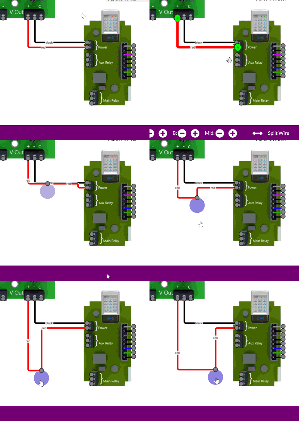
At the core of Techforce Pro is creating wiring diagrams.  You drag one terminal to another, change it's color, and you're done.  You can also manipulate it a little but there isn't much more you can do...Until now.


You had the ability to split wires on your customers floor plans already.  This feature was introduced there because the positioning of the wire is very important when viewing the wire's length.  However we found that you needed the ability to move wires around like that in the diagrams as well.


Splitting a wire adds the handle as you see in the above short animation.  Sometimes, the wire doesn't do exactly what you want when dragging the handle around, so we added the ability to rotate the handle changing how the wire and handle interact.  Rule of thumb: rotate the handle away from the direction that both parts are located, so in the animation below, the best rotation is down.


What makes splitting a wire in the diagram creator even sweeter?  Being able to drag a wire to the handle to create a splice point:


Monday, February 1, 2016

Techforce Pro Update: Changes to How You Wire Floor Plans


We have updated the way you create wires on your customer floor plans.  From your feedback, this update will make the task of creating your wire runs faster and easier.  The process is more intuitive as you never leave the view of the floor plan.


Simply hovering over the part or diagram will make the 4 arrows appear.  When you select a direction, all other part and diagram arrows will become visible for you to complete the wire run.  You will also have the option at the bottom to cancel the wire run if you change your mid or accidentally press an arrow.


With the arrows moved, clicking on a system or part will allow you to change the label.  Previously the items label was at the bottom of the page.  We moved it to the same location that the label is on the floor plan so it makes more sense.


Wednesday, December 23, 2015

Update: Give Me Some Slack!


The birds eye view of a wire run doesn't account for running up and down the wall, or running from one floor to another.  To accommodate this, there is a new input where you can type in a number to add to the calculated wire length.

Click on a wire to make it active, and enter a number into the "Wire Slack" number box.  Press the "Set" button to save the new value.  If you have split a wire into multiple wires, choose the wire with the length label and add slack to it.

With this new menu item, the wire menu started getting a bit crowded.  Some of the other menu items have been moved to a Wire Menu to the right:


This menu houses the "Split Wire", "Straighten", and the "Remove Wire" functions.

The tutorial videos have not been modified yet with this new layout but will soon.  We continue to add features so please keep the requests coming!


Thursday, December 3, 2015

Feature Update: Add Pictures of Customer Systems through Techforce Pro Mobile

Whether you are a technician troubleshooting a customers issue, or a sales rep doing a walk through, being able to attach real pictures to systems you install is vital when troubleshooting and integrating a system.

Techforce Pro is now the only software available that makes adding pictures to a customers file an easy task.  Simply find the system on the customers floor plan, and take a picture.  The picture is immediately available to anyone else viewing the customer through Techforce Pro Mobile, or TechforcePro.com.

First, find the system that you want to add a picture to.


In the section at the bottom, you can view existing pictures, or take new ones.


Clicking "Add Picture" opens the camera for you to take the picture.  Once the picture is taken, it is added to that systems pictures for viewing.

Clicking the picture thumbnail opens the picture full size for a more detailed view.


Open the system in TechforcePro.com and view the pictures there as well.


Sharing pictures has never been easier.  Seeing the system empowers your team to make better, faster decisions which ultimately makes for happy customers!

Tuesday, November 24, 2015

Tutorial: Adding Parts to Techforce Pro

Can't find a part you need.  Let us know and we'll get it in for you asap.  But if you can't wait, you can add your own parts to use in your wiring diagrams and as-builts.  To access your parts library, click your username in the upper right, and click on "Our Parts".

On the parts page, you can create organize your parts into Catalogs and Series.  A Part must be in a Catalog or a Series.

A Catalog holds Series and Parts, and a Series only holds Parts.  For example.  If I had a Catalog called "Managed Switches", I could have a set of Series called "5-Port", 8-Port"...  Inside the Series would be the actual parts.  Catalogs and Series have a folder icon, and Parts have a gear icon.


Click on one of the blue buttons along the top to create a new Catalog, Series, or Part


At least one Catalog is required.  Click the "New Catalog" button and complete the form.  The new Catalog will appear in the left menu automatically.


If you want, you can start adding Parts now.  Or if you need to add any sub-series to the Catalog, click the "New Series" button, and complete the form.  The only new item you see here is a check box for the Catalog you want to add the Series to.  You can add the Series to multiple Catalogs if you like.  For example, night vision camera's might go under a "Night Vision" Catalog, and a "Outdoor" Catalog.


Now the fun, adding Parts.  Click Add New Part to open the Part Creator.  There are two main sections. The part creator at the top is where you select the image, and add terminals. The details section below is where you enter a Title and Part Number, and select which Series and/or Catalogs the Part should appear in.  You can add this part to any number of Series or directly in Catalogs to help people find your parts easier.

Lets start with the top part and create the image and Terminals.


This is where you can choose your parts image, re-size the image if it is too large or small, and edit the terminals.  Start by clicking "Change Image" to open a file browser and find your picture.  The picture will appear in the same size that it will appear in the Diagram Editor.


We added a timer relay.  The thumbnail in the upper left is how this part will be displayed when added to a floor plan.  Now that we have the image, it can be re-sized if needed.  The main reason for re-sizing would be because the image is too large and takes up too much space on the wiring diagram, or it is too small and the terminals overlap.  We'll revisit this in a minute.  First let's add terminals.

Terminals are directional.  When you move parts around on the wiring diagram, you want the wires to maintain their direction so it is obvious where they are connected to.  The short animation below shows adding terminals to this part.


You can drag a terminal into place, or use the sliders for more precise placement.  Notice that when another terminal is added, it appears above the previous one.  This makes it easier when adding many terminals to one side.  Start by adding one to the bottom for the best use.  When adding terminals pointing up or down, they will appear to the right of the previous.

If your image is large, but has many terminals, you will still want to keep the image large enough so the terminals don't overlap.  The person making the wiring diagram will need to use a larger workbench to accommodate the larger part. 

If you find that you need to re-size the part after adding a few terminals, it would be easier to restart than re-size and move the existing terminals back into place.  Restart by refreshing the web page.  This short animation shows re-sizing the image.  Hold the shift key to maintain the aspect ratio.


That's the hard part.  All that's left is adding a title, part number, and choosing what Catalog(s) and Series this part will be displayed in.

One last important note: The parts are live in the wiring diagrams, so if you change an image, all diagrams will take on that new part image.  If you move terminals around, those will be moved in diagrams.  So once you create a part, be sure to make any edits right away before it is used.  You cannot delete parts, only obsolete them.  Obsolete parts will not show up in the diagram creator.

Wednesday, November 18, 2015

Browse Floor Plans and System Diagrams on Mobile!

Techforce Pro Mobile for Android has received an update on 11/18/15.  At first it may not look like much has changed.  But now, instead of just being able to view your jobs, you can browse all of your customers and system diagrams.

Clicking on the menu button, or swiping to the right opens up the menu


From the menu that appears, you can choose Systems, Customers, or Jobs, just like TechforcePro.com.  We'll start the tour by going into Customers:


Here is your full list of customers.  Use the search box to filter the list.  Clicking on a customer takes you to a details page:


Here you can see some basic details like the date this customer was added, the list of floor plans, and a full customer part list with images and quantities.  Clicking on a floor plan takes you to a page with more details about the floor plan.


You can get a preview of the floor's as-built diagram, along with a list of diagrams and the labels they have in the as-built.  Clicking on the as-built will take you to a full size image of the as-built where you can pinch to zoom and move around the floor plan to find what you are looking for.


Here you can see we found an electrical closet with a system number 13709.  To view this system in details, go back to the previous page, find the system and click on it.


Click on the System Diagram to view it in the image viewer to view it full size.


In fact, any image in TechforcePro Mobile can be sized larger for a better view.  Next, we go back to the side menu to enter the Systems page:


The Systems page has your list of systems that are not in a folder, those in folders will be coming soon.  These systems can be filtered by typing into the search box at the top.  Clicking on a system takes you to the system details page you saw previously where you get a part list and see the diagram full size.

That's it for this update.  Keep the suggestions coming!  Apple mobile update is coming soon.

Friday, October 30, 2015

Automatic Wire Run Lengths


Often, when creating the initial floor plan diagrams, you wire systems and parts together without regard to wire length.  The length a wire travels is a vital component to the functionality of your systems.  Wires have resistance and the voltage available at the other end of a DC wire run is not going to be the same as what is at the power supply.


Now, with Techforce Pro, your wire lengths are automatically available to you based on the scale you set to the floor plan.  To enable this, press Menu, then Settings:


In the settings menu, you will now see an option to Show Wire Lengths


Check this box and all of your wire runs will have a label indicating the distance based on the scale you set.  Remove the check to hide the lengths.


If your wire run has been split and includes handles, the entire run excluding the handles will be calculated and the label will appear near the middle of the whole wire run.  Change the scale, move parts and systems around and view all the numbers change automatically based on your changes.  

You will still need to know your own limitations but Techforce Pro now telling you the run lengths takes one more time consuming task out of your hands.


Tuesday, October 20, 2015

Feature Update: Shapes and Scale on the Floor Plan


This week, the new feature added to Techforce Pro is adding background shapes and adding a scale to your floor plan.  Adding shapes is helpful when showing the direction of a camera, the coverage area of a wireless receiver, or highlighting areas of the floor plan.

You can find the "Add Shapes" option under "Menu"


Here you see options to add geometric shapes, or enable free drawing.


After you add a shape, you can change interact with it directly to move it, rotate it, and re-size it.


Use the anchors around the shape to re-size it, and the one extending handle to rotate it.


Use the menu to change the shapes color and opacity (transparency).


All shapes appear behind diagrams, parts and wires.


Another item you can add is free drawn shapes.  First, make sure the area you want to draw on is visible on the screen.  The website has to lock the floor plan in place when free drawing so the floor plan doesn't move.

Next, Click "Enable Free Draw".  You can jot down a note, or circle a large area.


If you select a color, the free drawn shape will close it's path and fill in.  If you are jotting a note, you do not want to do this.


Any shape can be removed by selecting it and clicking "Remove" in the lower right corner so you can remove temporary notes later on.

The second update is adding a scale to your floor plan.  For now it is just a visual indication, but we plan on taking this a bit further in the near future, (like calculating wire run distances).

To show the scale, click on the menu and Settings.  A new section under "Scale" is where you can type in your inches to feet conversion.


When you press "Set Scale", a scale will appear in the upper left corner of the floor plan.


Fine tune this by dragging it to an area on the floor plan that you know the real distance, such as an 8 foot hallway, and better define the scale there.


When you have it right, drag the scale to it's final destination.  for any shape, to straighten it out, click the "Straighten" button to snap the shape, or the scale, to the closest 90deg rotation point.